ADT7463
http://onsemi.com
30
The fan tachometer readings are 16bit values consisting
of a 2byte read from the ADT7463.
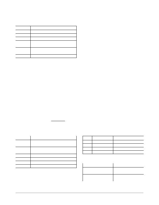
Table 34. FAN SPEED MEASUREMENT REGISTERS
Register
Description
Default
0x28
TACH1 Low Byte
0x00
0x29
TACH1 High Byte
0x00
0x2A
TACH2 Low Byte
0x00
0x2B
TACH2 High Byte
0x00
0x2C
TACH3 Low Byte
0x00
0x2D
TACH3 High Byte
0x00
0x2E
TACH4 Low Byte
0x00
0x2F
TACH4 High Byte
0x00
Reading Fan Speed from the ADT7463
If fan speeds are being measured, this involves a
2register read for each measurement. The low byte should
be read first. This causes the high byte to be frozen until both
high and low byte registers have been read from. This
prevents erroneous TACH readings.
The fan tachometer reading registers report back the
number of 11.11 ms period clocks (90 kHz oscillator) gated
to the fan speed counter, from the rising edge of the first fan
TACH pulse to the rising edge of the third fan TACH pulse
(assuming two pulses per revolution are being counted).
Since the device is essentially measuring the fan TACH
period, the higher the count value the slower the fan is
actually running. A 16bit fan tachometer reading of
0xFFFF indicates either that the fan has stalled or is running
very slowly (< 100 RPM).
HighLimit :u ComparisonPerformed
Since the actual fan TACH period is being measured,
exceeding a fan TACH limit by 1 sets the appropriate status
bit and can be used to generate an SMBALERT
.
The fan TACH limit registers are 16bit values consisting
of two bytes.
Table 35. FAN TACH LIMIT REGISTERS
Register
Description
Default
0x54
TACH1 Minimum Low Byte
0xFF
0x55
TACH1 Minimum High Byte
0xFF
0x56
TACH2 Minimum Low Byte
0xFF
0x57
TACH2 Minimum High Byte
0xFF
0x58
TACH3 Minimum Low Byte
0xFF
0x59
TACH3 Minimum High Byte
0xFF
0x5A
TACH4 Minimum Low Byte
0xFF
0x5B
TACH4 Minimum High Byte
0xFF
Fan Speed Measurement Rate
The fan TACH readings are normally updated once every
second.
The FAST bit (Bit 3) of Configuration Register 3
(Reg. 0x78), when set, updates the fan TACH readings every
250 ms.
If any of the fans are not being driven by a PWM channel
but are powered directly from 5 V or 12 V, its associated dc
bit in Configuration Register 3 should be set. This allows
TACH readings to be taken on a continuous basis for fans
connected directly to a dc source.
Calculating Fan Speed
Assuming a fan with a two pulses/revolution (and two
pulses/revolution being measured), fan speed is calculated
by:
Fan Speed (RPM) + (90,000 60)Fan TACH Reading
where:
Fan TACH Reading = 16bit Fan Tachometer Reading
Example:
TACH1 HIGH Byte (Reg. 0x29) + 0x17
TACH1 LOW Byte (Reg. 0x28) + 0xFF
What is Fan 1 speed in RPM?
Fan 1 TACH Reading + 0x17FF + 6143 Decimal
RPM + (f 60)Fan 1 TACH Reading
RPM + (90, 000 60)6143
Fan Speed + 879 RPM
Fan Pulses per Revolution
Different fan models can output either 1, 2, 3, or 4 Tach
pulses per revolution. Once the number of fan Tach pulses
has been determined, it is programmed into the fan pulses
per revolution register (Reg. 0x7B) for each fan.
Alternatively, this register can be used to determine the
number or pulses/revolution output by a given fan. By
plotting fan speed measurements at 100% speed with
different pulses/revolution setting, the smoothest graph with
the lowest ripple determines the correct pulses/revolution
value.
Table 36. FAN PULSES PER REVOLUTION REGISTER
(REG. 0X7B)
Bit
Mnemonic
Description
<1:0>
FAN1 Default
2 Pulses per Revolution
<3:2>
FAN2 Default
2 Pulses per Revolution
<5:4>
FAN3 Default
2 Pulses per Revolution
<7:6>
FAN4 Default
2 Pulses per Revolution
Table 37. FAN PULSES PER REVOLUTION
REGISTER BIT VALUES
Value
Description
00
1 Pulse per Revolution
01
2 Pulses per Revolution
10
3 Pulses per Revolution
11
4 Pulses per Revolution
发布紧急采购,3分钟左右您将得到回复。
相关PDF资料
ADT7476AARQZ-R
IC REMOTE THERMAL CTLR 24QSOP
ADT7481ARMZ-1RL
IC SENSOR TEMP 2CH ALARM 10MSOP
ADT7482ARMZ-REEL
IC SENSOR TEMP 2CH ALARM 10MSOP
ADT7485AARMZ-R
IC TEMP/VOLT DGL SENS SST 10MSOP
ADT7486AARMZ-RL
IC TEMP SENS DGTL 2CH SST 10MSOP
ADT7488AARMZ-RL
IC TEMP/VOLT DGTL W/SST 10MSOP
ADT7518ARQZ
IC SENSOR TEMP QD ADC/DAC 16QSOP
AT30TS00-MAH-T
SENSOR DGTL TEMP I2C/SMBUS 8WDFN
相关代理商/技术参数
ADT7463ARQZ-REEL7
功能描述:IC REMOTE THERMAL CTRLR 24-QSOP RoHS:是 类别:集成电路 (IC) >> PMIC - 热管理 系列:dBCool® 标准包装:1 系列:- 功能:温度监控系统(传感器) 传感器类型:内部和外部 感应温度:-40°C ~ 125°C,外部传感器 精确度:±2.5°C 本地(最大值),±5°C 远程(最大值) 拓扑:ADC,比较器,寄存器库 输出类型:2 线 SMBus? 输出警报:无 输出风扇:无 电源电压:2.7 V ~ 5.5 V 工作温度:-40°C ~ 125°C 安装类型:表面贴装 封装/外壳:SOT-23-8 供应商设备封装:SOT-23-8 包装:Digi-Reel® 其它名称:296-22675-6
ADT7466
制造商:AD 制造商全称:Analog Devices 功能描述:dBCool Remote Thermal Controller and Voltage Monitor
ADT7466ARQZ
功能描述:板上安装温度传感器 RMT THRM CTR VLT MON RoHS:否 制造商:Omron Electronics 输出类型:Digital 配置: 准确性:+/- 1.5 C, +/- 3 C 温度阈值: 数字输出 - 总线接口:2-Wire, I2C, SMBus 电源电压-最大:5.5 V 电源电压-最小:4.5 V 最大工作温度:+ 50 C 最小工作温度:0 C 关闭: 安装风格: 封装 / 箱体: 设备功能:Temperature and Humidity Sensor
ADT7466ARQZ-REEL
功能描述:板上安装温度传感器 RMT THRM CTR VLT MON RoHS:否 制造商:Omron Electronics 输出类型:Digital 配置: 准确性:+/- 1.5 C, +/- 3 C 温度阈值: 数字输出 - 总线接口:2-Wire, I2C, SMBus 电源电压-最大:5.5 V 电源电压-最小:4.5 V 最大工作温度:+ 50 C 最小工作温度:0 C 关闭: 安装风格: 封装 / 箱体: 设备功能:Temperature and Humidity Sensor
ADT7466ARQZ-REEL7
功能描述:IC REMOTE THERMAL CTRLR 16QSOP RoHS:是 类别:集成电路 (IC) >> PMIC - 热管理 系列:dBCool® 标准包装:1 系列:- 功能:温度监控系统(传感器) 传感器类型:内部和外部 感应温度:-40°C ~ 125°C,外部传感器 精确度:±2.5°C 本地(最大值),±5°C 远程(最大值) 拓扑:ADC,比较器,寄存器库 输出类型:2 线 SMBus? 输出警报:无 输出风扇:无 电源电压:2.7 V ~ 5.5 V 工作温度:-40°C ~ 125°C 安装类型:表面贴装 封装/外壳:SOT-23-8 供应商设备封装:SOT-23-8 包装:Digi-Reel® 其它名称:296-22675-6
ADT7466ARQZ-RL7
功能描述:板上安装温度传感器 RMT THRM CTR VLT MON RoHS:否 制造商:Omron Electronics 输出类型:Digital 配置: 准确性:+/- 1.5 C, +/- 3 C 温度阈值: 数字输出 - 总线接口:2-Wire, I2C, SMBus 电源电压-最大:5.5 V 电源电压-最小:4.5 V 最大工作温度:+ 50 C 最小工作温度:0 C 关闭: 安装风格: 封装 / 箱体: 设备功能:Temperature and Humidity Sensor
ADT7466ZEVB
功能描述:BOARD EVALUATION ADT7466 RoHS:是 类别:编程器,开发系统 >> 过时/停产零件编号 系列:dBCool® 标准包装:1 系列:- 传感器类型:CMOS 成像,彩色(RGB) 传感范围:WVGA 接口:I²C 灵敏度:60 fps 电源电压:5.7 V ~ 6.3 V 嵌入式:否 已供物品:成像器板 已用 IC / 零件:KAC-00401 相关产品:4H2099-ND - SENSOR IMAGE WVGA COLOR 48-PQFP4H2094-ND - SENSOR IMAGE WVGA MONO 48-PQFP
ADT7467
制造商:AD 制造商全称:Analog Devices 功能描述:dBCool Remote Thermal Monitor and Fan Controller